Modern measurement systems often operate with single 5-V power supplies, yet their input signals may have large common-mode voltages that exceed the supply by tens or hundreds of volts. Also, unless the converter is driven differentially, the noise on the analog-to-digital converter (ADC) reference pin is indistinguishable from a real signal.
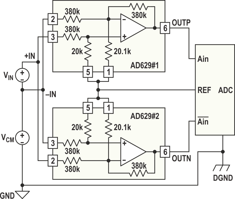
The circuit of Figure 1 solves both of these problems. It provides a gain of 2, along with differential inputs and a differential output. The ADC reference sets the output common-mode level. The amplifier is constructed with two subtractors, each compliant to high common-mode voltage. These subtractors are set up so that the positive input of one connects to the negative input of the other, and vice versa. Their reference pins are tied together and connected to the ADC's reference pin.
 |
|
| Figure 1. | Based on two single-supply amplifiers and an ADC, this circuit can measure small signals in the presence of high common-mode voltages. |
As the input signal increases, one output, OUTP, increases, while the other output, OUTN, decreases. Both outputs remain centered with respect to the common-mode level set by the ADC's reference.
Figure 2 illustrates the circuit's performance with a single 5-V power supply. At the top is a 1-kHz, 2-V p-p input signal. At the bottom are the two outputs in antiphase to produce a 4-V p-p signal centered around the 2.5-V reference.
 |
|
| Figure 2. | These waveforms show circuit performance with a single 5-V supply. The upper trace is the 1-kHz, 2-V p-p input signal, while the lower trace shows the two antiphase outputs, which produce a 4-V p-p signal centered around 2.5 V. |
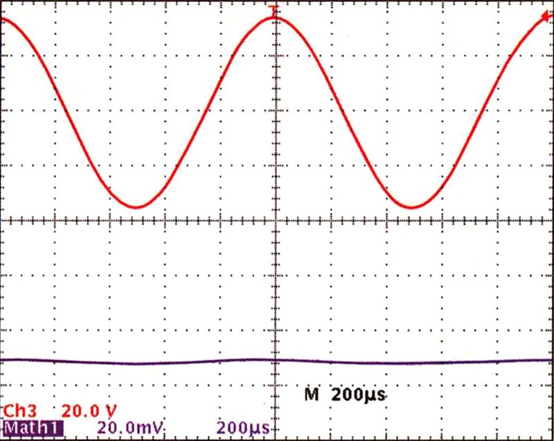
Figure 3 demonstrates the system's ability to reject a 1-kHz, 60-V p-p common-mode signal. The upper waveform shows the common-mode input, while the lower waveform shows the output.
 |
|
| Figure 3. | With a 5-V power supply and a 1-kHz, 60-V p-p common-mode signal (upper trace), the circuit’s output (lower trace) illustrates the high common-mode rejection. |
Bigger power supplies, such as ±15 V, can be used for larger common-mode signals. Figure 4 shows that the system can reject a 400-V p-p common-mode signal (upper waveform), with the residual error of less than 10 mV p-p shown in the lower waveform.
 |
|
| Figure 4. | Using a ±15-V supply, the circuit reduces a 400-V p-p common-mode signal (upper trace) to under 10 mV p-p (lower trace). |
